
An Oil and Gas Separator is a pressure vessel used to separate the different phases of fluids produced from oil and gas wells. These fluids often contain natural gas, crude oil, produced water, and solid particles.
Separating these components is an essential step in upstream production because each phase requires different treatment before entering downstream processing facilities. The efficiency of this separation process affects production stability,
What Is an Oil and Gas Separator?
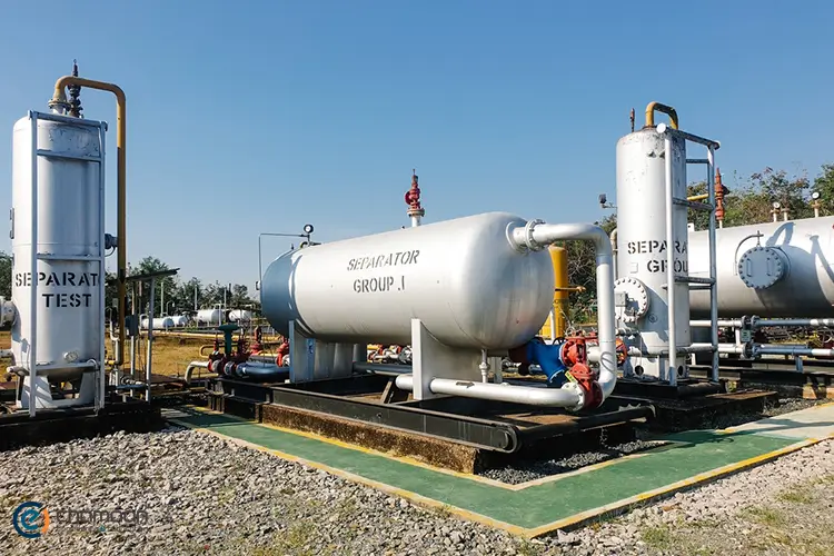
An oil and gas separator is a process vessel that divides a multiphase wellstream into individual fluid components. It is commonly installed near production wells or within processing facilities to prepare extracted fluids for further treatment.
The incoming stream may contain four main components:
- Natural Gas: The gaseous hydrocarbon fraction separated from the liquid stream.
- Crude Oil: The liquid hydrocarbon phase collected for further processing.
- Produced Water: Water extracted alongside hydrocarbons from the reservoir.
- Solids: Sand, sediment, and other particles carried by production fluids.
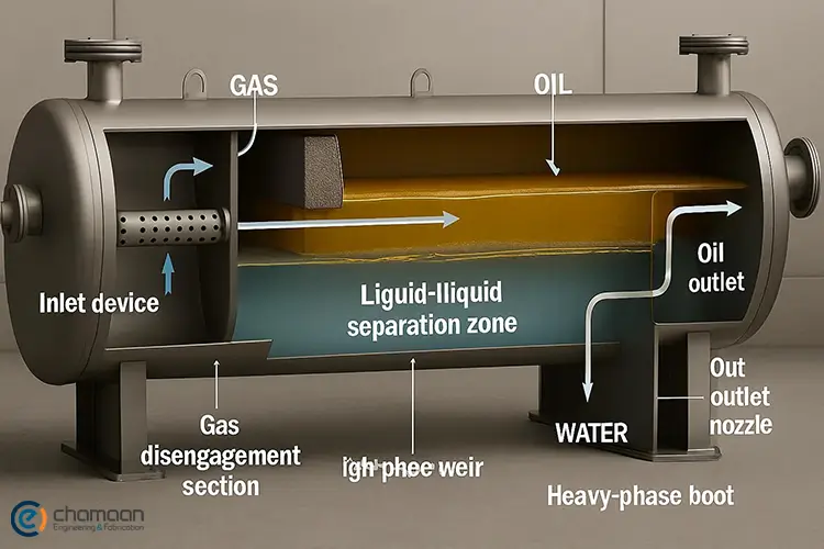
The separation mechanism primarily uses differences in density and fluid behavior. Gas moves toward the upper section of the vessel, while heavier liquids collect below. In three-phase configurations, oil and water form separate layers.
Several operating conditions influence separation performance. Pressure and temperature affect fluid properties, while residence time determines how long the phases remain inside the vessel. Flow velocity and turbulence must also be controlled to prevent liquid droplets from escaping with the gas stream.
The separated fluids can then enter dedicated treatment systems. For example, crude oil may undergo additional water and salt removal through a Desalter package, while the gas stream can be directed toward compression or further processing.
How Does an Oil and Gas Separator Work?
An oil and gas separator uses controlled fluid flow, gravity, and internal separation devices to divide a multiphase stream into gas and liquid components. The process begins when production fluids enter the vessel and continues until each separated phase reaches its designated outlet.
The typical operating sequence includes six stages:
- Inlet Distribution: The incoming wellstream enters through an inlet nozzle and encounters an inlet diverter.
- Momentum Reduction: The diverter changes the flow direction and reduces the energy of the incoming stream. This helps release bulk gas from the liquid.
- Primary Gas-Liquid Separation: Gas rises toward the upper section, while larger liquid droplets move downward.
- Liquid Separation: Oil and water separate through gravity when the vessel is designed for three-phase operation.
- Mist Removal: A demister captures fine liquid droplets that remain suspended in the gas.
- Phase Discharge: Control valves regulate the removal of gas, oil, and water through separate outlets.
The separation process does not rely exclusively on gravity. Inertial separation occurs when the inlet device changes the direction of the fluid. Coalescence helps smaller droplets combine into larger ones, making them easier to separate. Mist elimination provides an additional stage for removing liquid droplets from the gas outlet.
After primary separation, gas may require additional moisture removal in a Dehydration package before entering pipelines or other gas-processing equipment. The exact arrangement depends on the required gas quality and the facility’s process design.
Types of Separators in Oil and Gas Industry
Oil and gas separators have several configurations, and there is no single number that represents all their types. Engineers classify these vessels according to their physical orientation, the number of phases they separate, and their intended process application.
Classification Based on Vessel Orientation
The three commonly discussed vessel configurations are horizontal, vertical, and spherical separators. Their selection depends on liquid production rates, gas volume, available installation space, and separation requirements.
1. Horizontal Separator
A horizontal separator is a cylindrical pressure vessel installed parallel to the ground. Its geometry provides an extended liquid-gas interface and considerable liquid collection capacity.
This configuration is particularly suitable for liquid-dominated production streams and applications requiring oil-water separation. It also offers advantages when handling fluctuations in liquid production, provided the vessel has sufficient surge capacity.
Common applications include:
- Three-phase production separation.
- High liquid flow-rate operations.
- Production systems with intermittent liquid slugs.
- Facilities requiring additional liquid retention volume.
2. Vertical Separator
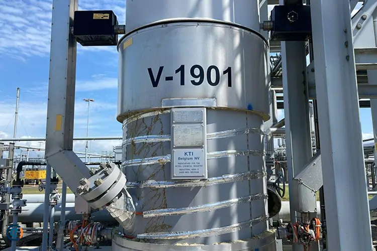
A vertical separator has an upright cylindrical structure. Its main advantage is a relatively small ground footprint, making it useful where installation space is limited.
These vessels are commonly selected for gas-rich streams because liquid droplets can fall toward the bottom while gas moves upward. Vertical configurations are also widely used in compressor scrubbers to remove entrained liquids before gas reaches compression equipment.
Their main limitation is installation height. Transportation, lifting, and maintenance may become more complicated in facilities with restricted vertical clearance.
3. Spherical Separator
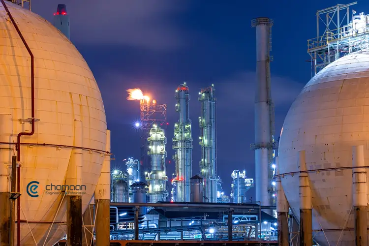
A spherical separator uses a rounded pressure vessel to accommodate gas-liquid separation in a compact structure. Its geometry offers favorable pressure-containment characteristics, but the available liquid storage volume is relatively limited.
For this reason, spherical separators have more specialized applications and are less common than horizontal and vertical designs in conventional production facilities.
Classification Based on Number of Phases
Another classification method focuses on the number of fluid phases leaving the vessel. From this perspective, the two principal configurations are two-phase and three-phase separators.
1. Two-Phase Separator
A two-phase separator divides the incoming production stream into gas and liquid. The liquid outlet may contain both crude oil and produced water because the vessel is not necessarily designed to separate these two liquids independently.
2. Three-Phase Separator
A three-phase separator produces three separate outlets: natural gas, crude oil, and produced water. Its internal arrangement allows the liquid phases to settle into different layers.
In many horizontal designs, a weir helps maintain the oil level, while a separate interface control system regulates the water level.
An important distinction is that vessel orientation and separation capacity are independent classifications. A vessel can therefore be a horizontal three-phase separator or a vertical two-phase separator.
Oil and Gas Separator Components
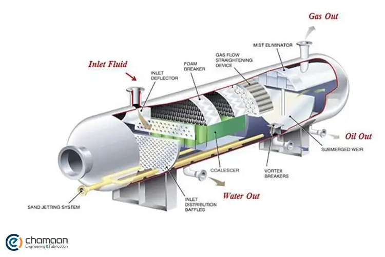
The internal and external components of an oil and gas separator work together to control fluid movement, remove entrained droplets, and maintain stable operating conditions. Their arrangement varies according to vessel configuration and process requirements.
The most important components include:
| Component | Main Function |
| Inlet Diverter | Changes the direction of incoming fluids and reduces their momentum. |
| Mist Extractor (Demister) | Captures fine liquid droplets from the gas stream. |
| Coalescing Plates | Encourage small droplets to combine into larger droplets. |
| Weir | Maintains the oil level and controls liquid movement in certain three-phase designs. |
| Pressure Control Valve | Regulates the pressure inside the vessel. |
| Level Control System | Monitors liquid levels and the oil-water interface. |
| Liquid Dump Valve | Controls the discharge of separated liquids. |
| Pressure Safety Valve (PSV) | Protects the vessel against excessive pressure. |
Not all separators require every component listed above. For example, a two-phase separator does not necessarily need an oil-water interface control system. Similarly, coalescing elements are included when the process requires additional separation capability.
The control system is particularly important because unstable pressure or liquid levels can affect downstream equipment. Depending on the facility design, separated gas may also be used in fuel systems, including Gas Furnaces, after meeting the relevant fuel-gas requirements.
How to Select the Right Oil and Gas Separator?
Choosing an appropriate oil and gas separator requires evaluating production data, fluid characteristics, operating conditions, and the required separation performance. An incorrectly sized vessel may cause excessive liquid carryover, poor oil-water separation, or unstable operation.
Engineers generally evaluate the following parameters:
| Selection Parameter | Why It Matters |
| Flow Rate | Determines the required gas and liquid handling capacity. |
| Operating Pressure | Influences gas density and phase behavior. |
| Operating Temperature | Affects fluid properties and separation conditions. |
| Gas-Liquid Ratio (GLR) | Helps establish the relative gas and liquid loads. |
| Fluid Properties | Density, viscosity, and surface tension influence droplet movement. |
| Liquid Slug Volume | Determines the required liquid surge capacity. |
| Installation Space | Helps determine vessel orientation and dimensions. |
| Separation Efficiency | Defines the acceptable level of liquid carryover and water content. |
| Material Selection | Accounts for corrosion, erosion, and operating conditions. |
The engineering process should also consider pressure drop, gas velocity, liquid retention time, and the performance of internal devices.
API RP 12J:2024, ninth edition, is an important engineering reference for the process design of oil and gas separators and scrubbers. It covers conventional separation internals and design considerations for different vessel arrangements.
Applications of Oil and Gas Separators
Oil and gas separators are used throughout production and processing facilities wherever multiphase fluids need to be divided before further treatment. Their applications extend from wellhead installations to offshore platforms, gas processing plants, refineries, and compressor stations.
Their position within a process facility depends on the required treatment sequence. For example:
- Upstream Production: Separators remove free gas and liquids from wellstream fluids before further processing.
- Crude Oil Treatment: Separated crude may enter a desalter or other treatment equipment to reduce water and salt content.
- Gas Processing: Gas streams may pass through dehydration and purification systems to meet pipeline or process specifications.
- Chemical Treatment: A chemical injection package can introduce corrosion inhibitors, demulsifiers, and other chemicals into designated process streams.
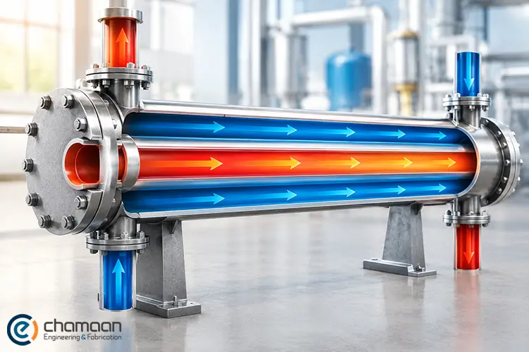
- Thermal Processing: Process fluids may require temperature adjustment using equipment such as a Double Pipe Heat Exchanger.
Conclusion
Oil and gas separators are essential for controlling multiphase production streams and preparing fluids for downstream operations.
For guidance on selecting the right oil and gas separator for your facility, you can contact the experts at Chamaan. Our specialists can help you evaluate your process requirements and identify suitable process equipment for your project.
Reach out to the Chamaan team to receive professional consultation and make more informed decisions about your oil and gas processing needs.